Blame
| 2f506a | Peter van Dijk | 2026-01-28 19:04:41 | 1 | # Nebra Outdoor |
| f3238b | Peter van Dijk | 2026-01-28 19:05:57 | 2 | |
| 25669d | Peter van Dijk | 2026-01-28 21:08:40 | 3 | ## wio sx1262 board on 'hat' header, for pymc_repeater or meshtasticd |
| 120e05 | Peter van Dijk | 2026-01-28 20:01:07 | 4 | |
| 5 | [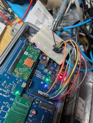](./nebra-pinheader-sx1262-photo.jpg) |
|||
| 6 | [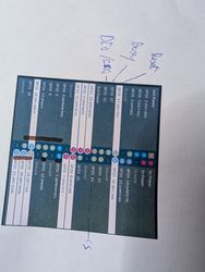](./nebra-pinheader-sx1262-pinout-note.jpg) |
|||
| 7 | ||||
| 8 | This pinout is inspired by/compatible with the [Zebra Hat](https://github.com/wehooper4/Meshtastic-Hardware/tree/main/ZebraHAT). The Zebra Hat is different from other LoRa hats because it considers the limited number of actually connected pins in the Nebra miner. By being compatible with that board, after connecting all the wires, [pyMC_Repeater](https://github.com/rightup/pyMC_Repeater) just works when picking the Zebra Hat board type. |
|||
| 9 | ||||
| 10 | Full pinout description (you can use [pinout.xyz](https://pinout.xyz/pinout/spi) instead of the second photo above): |
|||
| 11 | ||||
| 769cae | Peter van Dijk | 2026-01-28 20:08:32 | 12 | | SX1262 pin | Nebra/Pi GPIO number | Nebra/Pi pin name | Nebra/Pi pin number | |
| 13 | | -------- | -------- | -------- | -------- | |
|||
| 14 | | GND | - | Ground | 9 or [some other ground pin](https://pinout.xyz/pinout/ground) | |
|||
| 15 | | RST | 17 | GPIO 17 | 11 | |
|||
| 16 | | BUSY | 27 | GPIO 27 | 13 | |
|||
| 17 | | DIO1 | 22 | GPIO 22 | 15 | |
|||
| 18 | | 3V3 | - | 3v3 Power | 17 or 1 | |
|||
| 19 | | MOSI | 10 | SPI0 MOSI | 19 | |
|||
| 20 | | MISO | 9 | SPI0 MISO | 21 | |
|||
| 21 | | SCK | 23 | SPI0 SCLK | 23 | |
|||
| 22 | | NSS | 24 | GPIO 24 | 18 | |
|||
| 23 | ||||
| 24 | If you use 17 and 9 for 3V3 and GND, all pins are in a single straight line except for the NSS one on GPIO24. |
|||
| 25 | SX1262 RF_SW, VIN, and pins like D5, D6, D7, do not need to be connected. |
|||
| 120e05 | Peter van Dijk | 2026-01-28 20:01:07 | 26 | |
| f3238b | Peter van Dijk | 2026-01-28 19:05:57 | 27 | # unsorted notes, to be sorted |
| 28 | ||||
| 29 | via https://helium.nebra.com/datasheets/hotspots/outdoor/Nebra%20Outdoor%20Hotspot%20Datasheet.pdf |
|||
| 30 | ||||
| 31 | has two: |
|||
| 32 | ||||
| 33 | > Lora Module Connector - Designed for use with select M-PCIE LoRa Concentrators, these only have wired up SPI, plus GPS PPS from the GPS Module |
|||
| 34 | ||||
| 35 | it also has one slot with just USB wired up (and the SIM and ....) |
|||
| 36 | ||||
| 37 | But now I wonder if we can replace the entire Pi CM(3) daughterboard with some esp or nrf plus semtech 1262 kit to even avoid the power draw of a pi - depending on use case, of course. Answer: we can remove the cm3 and still get all power pins. |
|||
| 38 | ||||
| 39 | https://github.com/wehooper4/Meshtastic-Hardware/tree/main/NebraHat |
|||
| 40 | ||||
| 41 | https://github.com/wirenboard/atecc-util |
|||
| 42 | ||||
| 43 | https://github.com/pinztrek/nebra-hnt-meshtasticd - mentioned waveshare board might be https://www.waveshare.com/sx1262-868m-lora-hat.htm, also https://m.youtube.com/watch?v=hJv9Xv6PUJ4 plus https://www.youtube.com/watch?v=OrHVr8An9Io |
|||
| 44 | ||||
| 45 | https://meshtastic.org/blog/a-major-solution-to-a-miner-problem/ |
|||
| 46 | ||||
| 47 | ### usb hub (bt/wifi) daughter board |
|||
| 48 | ||||
| 49 | appears to get usb over an actual usb cable from a usb port on the mainboard. the 40 pin header only appears to have a few pins connected: |
|||
| 50 | ||||
| 51 | * 1 (3v3), going to ECC1 and other things |
|||
| 52 | * 22 (gpio25, going to LED1) |
|||
| 53 | * 17? going to a button |
|||
| 54 | * two more low-numbered pins going to ECC1, probably 2 (I2C1 SDA) and 3 (I2C1 SCL) |
|||
| 55 | ||||
| 56 | ### exar ethernet/i2c/gpio |
|||
| 57 | ||||
| 58 | ``` |
|||
| 59 | Bus 001 Device 005: ID 04e2:1300 Exar Corp. XR2280x 10/100 Ethernet |
|||
| 60 | Bus 001 Device 006: ID 04e2:1100 Exar Corp. XR2280x I2C Controller |
|||
| 61 | Bus 001 Device 007: ID 04e2:1200 Exar Corp. XR2280x GPIO Controller |
|||
| 62 | ``` |
|||
| 63 | ||||
| 64 | ||||
| 65 | ||||
| 66 | ### power draw |
|||
| 67 | ||||
| 68 | each section here is an incremental change from the previous one |
|||
| 69 | ||||
| 70 | #### stock miner, BT dongle removed, heltec v3 plugged in |
|||
| 71 | ||||
| 72 | 5-7W |
|||
| 73 | ||||
| 74 | ``` |
|||
| 75 | peter@tabantha:~ $ lsusb -t |
|||
| 76 | /: Bus 001.Port 001: Dev 001, Class=root_hub, Driver=dwc_otg/1p, 480M |
|||
| 77 | |__ Port 001: Dev 002, If 0, Class=Hub, Driver=hub/4p, 480M |
|||
| 78 | |__ Port 001: Dev 003, If 0, Class=Hub, Driver=hub/7p, 480M |
|||
| 79 | |__ Port 001: Dev 005, If 0, Class=Communications, Driver=cdc_ether, 480M |
|||
| 80 | |__ Port 001: Dev 005, If 1, Class=CDC Data, Driver=cdc_ether, 480M |
|||
| 81 | |__ Port 006: Dev 006, If 0, Class=Human Interface Device, Driver=usbhid, 480M |
|||
| 82 | |__ Port 007: Dev 008, If 0, Class=Human Interface Device, Driver=usbhid, 480M |
|||
| 83 | |__ Port 003: Dev 004, If 0, Class=Hub, Driver=hub/4p, 480M |
|||
| 84 | |__ Port 001: Dev 007, If 0, Class=Vendor Specific Class, Driver=rtl8xxxu, 480M |
|||
| 85 | |__ Port 002: Dev 009, If 0, Class=Vendor Specific Class, Driver=cp210x, 12M |
|||
| 86 | ``` |
|||
| 87 | ||||
| 88 | #### remove wifi |
|||
| 89 | ||||
| 90 | 4W |
|||
| 91 | ||||
| 92 | ``` |
|||
| 93 | peter@tabantha:~ $ lsusb -t |
|||
| 94 | /: Bus 001.Port 001: Dev 001, Class=root_hub, Driver=dwc_otg/1p, 480M |
|||
| 95 | |__ Port 001: Dev 002, If 0, Class=Hub, Driver=hub/4p, 480M |
|||
| 96 | |__ Port 001: Dev 003, If 0, Class=Hub, Driver=hub/7p, 480M |
|||
| 97 | |__ Port 001: Dev 005, If 0, Class=Communications, Driver=cdc_ether, 480M |
|||
| 98 | |__ Port 001: Dev 005, If 1, Class=CDC Data, Driver=cdc_ether, 480M |
|||
| 99 | |__ Port 006: Dev 006, If 0, Class=Human Interface Device, Driver=usbhid, 480M |
|||
| 100 | |__ Port 007: Dev 008, If 0, Class=Human Interface Device, Driver=usbhid, 480M |
|||
| 101 | |__ Port 003: Dev 004, If 0, Class=Hub, Driver=hub/4p, 480M |
|||
| 102 | |__ Port 002: Dev 007, If 0, Class=Vendor Specific Class, Driver=cp210x, 12M |
|||
| 103 | ``` |
|||
| 104 | ||||
| 105 | #### remove heltec |
|||
| 106 | ||||
| 107 | 4-5W |
|||
| 108 | ||||
| 109 | ``` |
|||
| 110 | peter@tabantha:~ $ lsusb -t |
|||
| 111 | /: Bus 001.Port 001: Dev 001, Class=root_hub, Driver=dwc_otg/1p, 480M |
|||
| 112 | |__ Port 001: Dev 002, If 0, Class=Hub, Driver=hub/4p, 480M |
|||
| 113 | |__ Port 001: Dev 003, If 0, Class=Hub, Driver=hub/7p, 480M |
|||
| 114 | |__ Port 001: Dev 005, If 0, Class=Communications, Driver=cdc_ether, 480M |
|||
| 115 | |__ Port 001: Dev 005, If 1, Class=CDC Data, Driver=cdc_ether, 480M |
|||
| 116 | |__ Port 006: Dev 006, If 0, Class=Human Interface Device, Driver=usbhid, 480M |
|||
| 117 | |__ Port 007: Dev 008, If 0, Class=Human Interface Device, Driver=usbhid, 480M |
|||
| 118 | |__ Port 003: Dev 004, If 0, Class=Hub, Driver=hub/4p, 480M |
|||
| 119 | ``` |
|||
| 120 | ||||
| 121 | #### remove usb daughterboard (the one with bt/wifi labels on it) from pin header |
|||
| 122 | ||||
| 123 | 3.5-6W |
|||
| 124 | ||||
| 125 | ``` |
|||
| 126 | peter@tabantha:~ $ lsusb -t |
|||
| 127 | /: Bus 001.Port 001: Dev 001, Class=root_hub, Driver=dwc_otg/1p, 480M |
|||
| 128 | |__ Port 001: Dev 002, If 0, Class=Hub, Driver=hub/4p, 480M |
|||
| 129 | |__ Port 001: Dev 003, If 0, Class=Hub, Driver=hub/7p, 480M |
|||
| 130 | |__ Port 001: Dev 005, If 0, Class=Communications, Driver=cdc_ether, 480M |
|||
| 131 | |__ Port 001: Dev 005, If 1, Class=CDC Data, Driver=cdc_ether, 480M |
|||
| 132 | |__ Port 006: Dev 006, If 0, Class=Human Interface Device, Driver=usbhid, 480M |
|||
| 133 | |__ Port 007: Dev 007, If 0, Class=Human Interface Device, Driver=usbhid, 480M |
|||
| 134 | |__ Port 003: Dev 004, If 0, Class=Hub, Driver=hub/4p, 480M |
|||
| 135 | ``` |
|||
| 136 | ||||
| 137 | #### also remove it from usb socket |
|||
| 138 | ||||
| 139 | ``` |
|||
| 140 | peter@tabantha:~ $ lsusb -t |
|||
| 141 | /: Bus 001.Port 001: Dev 001, Class=root_hub, Driver=dwc_otg/1p, 480M |
|||
| 142 | |__ Port 001: Dev 002, If 0, Class=Hub, Driver=hub/4p, 480M |
|||
| 143 | |__ Port 001: Dev 003, If 0, Class=Hub, Driver=hub/7p, 480M |
|||
| 144 | |__ Port 001: Dev 005, If 0, Class=Communications, Driver=cdc_ether, 480M |
|||
| 145 | |__ Port 001: Dev 005, If 1, Class=CDC Data, Driver=cdc_ether, 480M |
|||
| 146 | |__ Port 006: Dev 006, If 0, Class=Human Interface Device, Driver=usbhid, 480M |
|||
| 147 | |__ Port 007: Dev 007, If 0, Class=Human Interface Device, Driver=usbhid, 480M |
|||
| 148 | ||||
| 149 | ``` |
|||
| 150 | ||||
| 151 | #### pop cm3 out of socket |
|||
| 152 | ||||
| 153 | 1.5-3W |
|||
| 154 | ||||
| 155 | #### connect usb daughterboard back (just on usb, not pin header), with heltec connected to it |
|||
| 156 | ||||
| 157 | 3.5W (the heltec works) |
|||
| 158 | ||||
| 159 | #### remove everything that is unpluggable |
|||
| 160 | ||||
| 161 | unifi refuses to measure |
|||
| 162 | ||||
| 163 | #### plug heltec in mainboard usb socket |
|||
| 164 | ||||
| 165 | heltec works. |
|||
| 166 | ||||
| 167 | unifi refuses to measure |
|||
| 168 | ||||
| 169 | #### insert minipcie usb adapter board from aliexpress, move heltec to it |
|||
| 170 | ||||
| 171 | heltec works. no unifi measurement. |
|||
| 172 | ||||
| 173 | #### put back cm3 carrier with cm3 module and eMMC key |
|||
| 174 | ||||
| 175 | 4W |
|||
| 176 | ||||
| 177 | heltec works, serial to it works. |
|||
| 178 | ||||
| 179 | ``` |
|||
| 180 | peter@tabantha:~ $ lsusb -t |
|||
| 181 | /: Bus 001.Port 001: Dev 001, Class=root_hub, Driver=dwc_otg/1p, 480M |
|||
| 182 | |__ Port 001: Dev 002, If 0, Class=Hub, Driver=hub/4p, 480M |
|||
| 183 | |__ Port 001: Dev 003, If 0, Class=Hub, Driver=hub/7p, 480M |
|||
| 184 | |__ Port 001: Dev 005, If 0, Class=Communications, Driver=cdc_ether, 480M |
|||
| 185 | |__ Port 001: Dev 005, If 1, Class=CDC Data, Driver=cdc_ether, 480M |
|||
| 186 | |__ Port 006: Dev 006, If 0, Class=Human Interface Device, Driver=usbhid, 480M |
|||
| 187 | |__ Port 007: Dev 007, If 0, Class=Human Interface Device, Driver=usbhid, 480M |
|||
| 188 | |__ Port 002: Dev 004, If 0, Class=Vendor Specific Class, Driver=cp210x, 12M |
|||
| 189 | ``` |
|||
| 032010 | Peter van Dijk | 2026-01-28 23:19:46 | 190 | |
| 191 | # nebra miner minipcie pin count |
|||
| 192 | ||||
| 193 | [Nebra](https://github.com/NebraLtd/nebra-lora-hardware/blob/master/Smart-Outdoor-Mainboard-V1/HARDWARE/Pi%20Supply%20Smart%20LoRa%20Gateway%20Schematic.pdf) gives us, per minipcie slot, SCLK+MISO+MOSI+CE+RST. [lora-pipe config.h](https://github.com/folkertvanheusden/lora-pipe/blob/master/config.h) suggests we want SCLK+MISO+MOSI (+CE but maybe we can get away without it)+DIO1(interrupt)+RST. We also need BUSY, for a total of 7 pins. If we hardware CE to always be on, we free up one pin, giving us exactly enough to put DIO0+RST on? Turns out this is "not legal". One more pin if we can abuse GPS_PPS but I don't think we can (or if we can, it would still be shared between the two lora minipcie slots). |
|||
| 194 | ||||
| 195 | From `hpux735` on the meshcore discord: how about an i2c port expander? 5 pins fits SCLK/MISO/MOSI and all of I2C. You'd have to poll the IRQ. (Or maybe if I'm polling anyway, who needs the IRQ). |
|||
| 196 | ||||
| 197 | From `Mike's Allotment` on the meshcore discord: UART module instead of SPI? |
|||
| 198 | ||||
| 199 | Full pin list: |
|||
| 200 | ||||
| 201 | * SCLK |
|||
| 202 | * MISO |
|||
| 203 | * MOSI |
|||
| 204 | * CE |
|||
| 205 | * IRQ |
|||
| 206 | * BUSY |
|||
| 207 | * RST |
|||
| 208 | ||||
| 209 | Wired pins on Nebra: |
|||
| 210 | ||||
| 211 | * SCLK |
|||
| 212 | * MISO |
|||
| 213 | * MOSI |
|||
| 214 | * CE |
|||
| 215 | * RST |
|||
| 216 | ||||
| 217 | What if CE, when disasserted, makes BUSY readable on the RST pin, and when asserted, makes RST writable on the RST pin? I wonder what RST with CE asserted means. |
|||
| 218 | ||||
| 219 | MISO is inactive when CE is off, and CE is always off if BUSY is on. |
|||
| 220 | ||||
| 221 | What if KISS (TNC) over SPI, or UART bitbang, with a simple MCU. |
|||
| 222 | ||||
| 223 | What if SPI but something is interposing/reading along to pick up a special frame that means RESET. Then we can reuse the RST pin for BUSY. IRQ was always optional. |
|||
| 224 | ||||
| 225 | https://github.com/thekakester/Arduino-LoRa-Sx1262/blob/main/src/LoraSx1262.cpp#L230 -suggests- that BUSY can be inferred from GetStatus. This seems to be right for "Transmission is done" but I'm unsure it works for all busy reasons. |
|||
| 226 | ||||
| 227 | https://www.haraldkreuzer.net/en/news/LoRa-with-the-ESP32-and-Semtech-SX1262 is a very good page that tells us that TxDone and RxDone can be polled instead of IRQed. |